

Radio Servicing Information
For use by legally qualified and licensed repairers only
Countries have laws regulating who is legally allowed to repair or work on electrical equipment that will be plugged into the mains electricity supply. This is to protect the public from the risk of electric shock. If you are not lawfully allowed to repair electrical equipment yourself, you must find an electrician, a licensed electrical mechanic or electrical contractor or electronic technician to do any work on the equipment.
Different countries use electricity supply at different voltages. The United States uses 110-120 volts AC. The United Kingdom and Australia (amongst many other countries) uses 240 volts AC. Any electric shock at Voltage 110v or above is likely to be lethal.
Many types of early consumer electronic equipment was constructed at a time when electrical safety was not as carefully considered as is required under manufacturing laws today, and many early radio sets etc have mains electricity wiring and metal mains voltage terminals fully exposed to be touched once the metal chassis is removed from the wooden case or bakelite housing.
This is why any electrical work to restore or repair an old radio must be done by a licensed qualified technician.
YOU MUST NOT ATTEMPT TO REPAIR THE RADIO YOURSELF UNLESS YOU ARE LEGALLY ALLOWED TO DO SO.
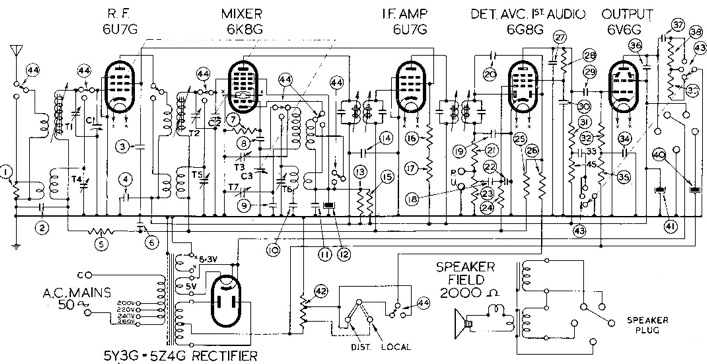
UNUSUAL SUPERHETERODYNES
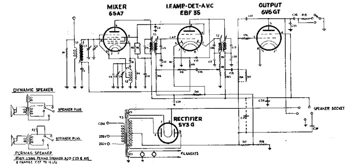
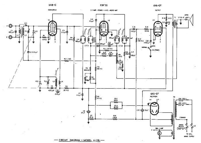
Most superheterodyne receivers follow the normal functions, a mixer/oscillator, an IF amplifier, a Detector/AGC/AF preamplifier, and audio power amplifier. There are some variations, additions, and performance enhancements.
R.F. AMPLIFIERS
In country areas, an extra amplifier valve is added before the mixer, to add gain. This is normally very similar to the IF amplifier, except that it has tuned grid and plate circuits, rather than the fixed IF transformers. It normally has AGC on it. There has to be an extra gang on the tuning capacitor. The valve chosen is often the same as the IF valve, but in some cases can be a low noise, or a valve suitable for HF. The faults can be the same as the mixer and IF stages, namely high resistors causing low gain, faulty bypass capacitors causing, instability, low gain or motor-boating.
MULTI-BAND OR SHORT WAVE RADIOS
For short or long wave reception, there is a band switch which has a mixer, and oscillator coil for each frequency band. This is a complicated switch, as it must connect all the coils, but without them interfering with each other. The designs ensure low stray capacity and there are many different approaches to this problem. The switches and coils are often hard to access and clean. For short wave reception, a mixer and RF amplifier suitable for HF are chosen. For Long Wave reception, there may be filters, to prevent noise and interference form getting in. Other than this complication, the mixer oscillator and RF amplifier (if fitted) suffer the same normal faults. If one band works and others do not, look for a dirty switch or damaged coil and contact, due to a lightning strike. WD40 is not a good switch cleaner, as it leaves a residue. Deoxit or CRC is better.
SENSITIVITY
The sensitivity of a broadcast band radio for city use, can be about 1000 microvolts. The sensitivity of a country or short wave radio (with an RF amplifier) is can be about 100 microvolts. Don't expect too much performance, as these are not communications receivers.
AERIALS/ANTENNAS
A normal valve radio will work quite well in a city, with a short length of wire connected to the aerial post, and lying on the floor. If you are located away from strong stations, then attach a longer wire and run it along a picture rail, if you have one. Otherwise, run it along a wall at floor level. This doesn't work too well for concrete floors or houses built into a hill side. If you have an underfloor space in a wooden house, run it along the bearers, but not near pipes as they are earthy and reduce the signal, or near electrical wires as they introduce noise. If you have a roof cavity (in a non metal roof), run it inside the roof. Avoid any metal parts including gutters. In a brick building or in multi-dwelling situation, run it out the window.
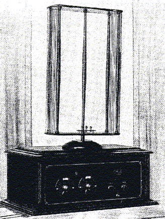
Some radios had an internal or external loop aerial, and often it was part of a tuned circuit. Check for open circuit windings. These were often directional, so rotating the radio may increase the signal, or enable you to reduce interference. In later models, the wire loop may be replaced with a ferrite rod. This works in the same way, but is smaller. If the rod is broken, glue it back together with a non conductive splint, and check that the inductance has not changed. If so retune it. It often doesn't matter.
IMAGING
The IF frequency of early radios was low (175 khz) and so there could be and "image" of a strong station appear on the dial where it should not. This is sometimes called "double spotting". This is the design of these radios, and can not be considered as a fault. Some of these radios may have two tuned circuits before the mixer, and so have a triple tuning gang. If there is an image on a radio with a 455 khz IF, then look for a misaligned aerial coil (selecting the wrong frequency), misaligned or faulty IF transformer. Another but not usual fault, is an oscillator that is running at the wrong frequency, or that has an impure waveform with many harmonics, and these are selecting another station. The common situation of all of these, is that the interfering station is strong. If the station is there, independently of tuning the dial, then it is breaking through without the help of the oscillator, and will be getting into the mixer or IF amplifier. Ensure the IF amplifier is not oscillating, and that there are not corroded connections anywhere, particularly shielding. If it is breakthrough of an FM or TV station, then this may not be a radio fault, but that the radio was never intended, to operate in those high signal levels. Adding a trap can assist, but will probably never completely cure this problem. Do not assume the IF frequency is always 455 khz, there were several other common IF frequencies.
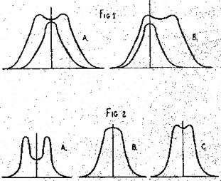
SELECTIVITY
The ability of a radio to select a station and not have adjacent stations ,interfering is the selectivity. This is achieved through the IF transformer design. The transformer has two windings, and if they are close together, there is broad selectivity. This also allows a better audio frequency response. If the two windings are further apart, the selectivityis sharper, but the audio response may be less. Some radios may have a mechanical method of moving the coils closer together. Another way is to switch in more windings, or more coupling capacity. A way to broaden the selectivity is to add a resistor across one winding. Check that the windings move properly(if mechanical), or that they are not open circuit or reverse connected (if extra windings), or if the capacitors are not faulty or out of tolerance (if capacity coupling).
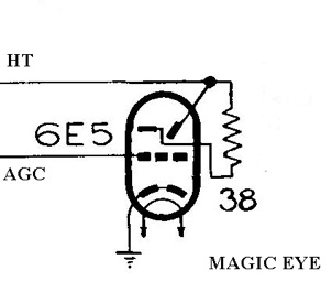
MAGIC EYE TUBES
This is a device that indicates signal strength. It has a display, usually in the form of a circle. There are different shapes. There is a resistor between the target and anode. It has its grid connected to the AGC line. As the grid voltage becomes more negative, the current in the tube drops, and there is less voltage drop across the target resistor, so the circle closes. Common faults are a dim display because the phosphor has worn out, and a high target resistor can cause little deflection. Make sure the AGC is working properly first.
REFLEXING
When valves were expensive, a cost saving method, was to make a valve perform two functions. The IF amplifier, would amplify the 455 khz IF signal, then also amplify the audio signal. Since they were at different frequencies, they did not interfere with each other. The IF output is detected, then fed back to the input and amplified again. This stage was designed very carefully, as it could easily oscillate, or overload and cause distortion. They were set up at the factory. When a valve was replaced, the stage might become unstable. There was usually a fixed trimmer capacitor, to control this. Curing instability or distortion may require, selecting the valve, adjusting the trimmer, or reducing the gain.
AUDIO AMPLIFIERS
The audio section of a radio can be have the frequency response improved by providing negative feedback. The response can be flattened or compensate for speaker deficiencies. Some audio signal is collected from the output, usually from the speaker transformer secondary. This signal is filtered with a resistance capacitance network, and applied out of phase to the cathode of the audio preamplifier. A tone control is sometimes in this network. Alternatively, it may be applied to the bottom of the volume control. A simple design providing negative feedback, was a cathode bias system, but with no cathode bypass capacitor.
If the speaker secondary is reversed, this can cause oscillation, or if the earthy end is lifted, there can be no feedback (or perhaps oscillation). Faulty capacitors and resistors affect the feedback frequency.
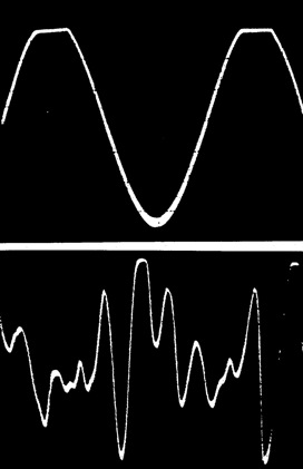
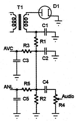
The AGC and the detector diode may be connected together in some cheaper radio designs. This can cause unbalanced clipping (on one cycle) at the detector. On strong signals, the large AGC voltage biases the detector diode, and it may bottom and will clip a large audio peak. This is in the design and is not a fault.
The audio section can also have a large power amplifier, with 2 output valves. These are normally connected in push-pull and can provide a large audio output. They require some method of phase change, so that each valve works for half the cycle. A balanced driver transformer, or a dedicated phase inverter (or "splitter") is required. Grid bias is important to set the class of the output valves. Cathode bias is common, but a separate bias supply is sometimes added in higher quality amplifiers. If distortion occurs, check the bias supply, leaking coupling capacitors, or a faulty transformer, as it may have shorted turns or an open winding. Look for any unbalance with an oscilloscope.
Tapped tone controls are used to boost the low frequencies at low volumes, to compensate for a frequency roll off in the human ear. This is called loudness compensation.
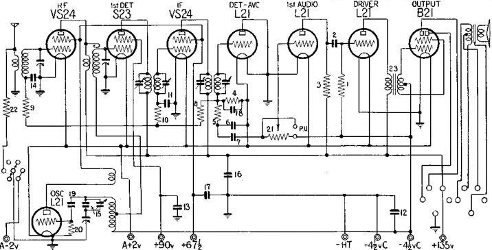
SEPARATE OSCILLATORS
In some early superheterodyne receivers, there was a separate oscillator valve, as pentagrid converters had not yet appeared. Check the grid as it should generate a negative voltage when oscillating. If checking it with a multimeter causes it to stop oscillating, lift the earthy end of the grid resistor and measure the grid current. Common faults are low emission and high resistors.
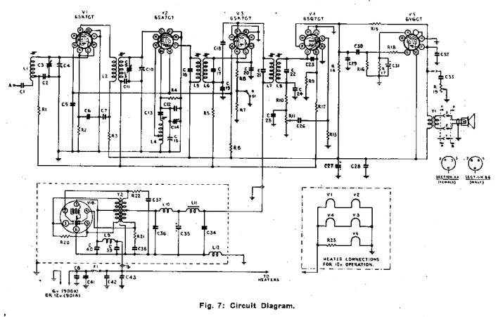
CAR RADIOS
These are a normal superheterodyne receiver running from a vibrator power supply. The radio is usually built more rugged to withstand vibration. There is filtering in the battery line and the aerial lead to prevent electrical noise from entering the radio. The aerial has extra inductance to match a short vertical whip aerial. Some models may have a noise limiter to clip or blank noise pulses. Other models may have an RF amplifier. Early car radios may have 6 volt electromagnetic speakers. The tuning could be a normal tuning capacitor in earlier models, or a ferrite slug tuning the coils in push button models. Common faults are cracks and breaks in components and wires. Also capacitors and resistors will get out of tolerance because of the heat, the inside of a car is subjected to. Be careful of radios that may have the power connected to the chassis, as some cars had positive earth systems and the radios were different.
FARM RADIOS
Radios designed for farms, are commonly designed for 32 volts DC. They may use a vibrator to provide the HT. They may also be of an unusual design and use the 32 volts DC directly as the HT tension. This removes the need for a high voltage supply. The valve gain is not as good at this low voltage, so there may be an extra RF, IF or AF amplifier stage. The valves must be in good condition to function well with a low HT, especially the mixer, so check the emission if gain is low. The HT capacitors are not subjected to high voltage, so may not fail due to break-down, but may fail due to age.
Section 1
Section 2
Section 3
Section 4
Section 5
Section 6
Section 7
Section 8
Section 9