

Radio Servicing Information
For use by legally qualified and licensed repairers only
Countries have laws regulating who is legally allowed to repair or work on electrical equipment that will be plugged into the mains electricity supply. This is to protect the public from the risk of electric shock. If you are not lawfully allowed to repair electrical equipment yourself, you must find an electrician, a licensed electrical mechanic or electrical contractor or electronic technician to do any work on the equipment.
Different countries use electricity supply at different voltages. The United States uses 110-120 volts AC. The United Kingdom and Australia (amongst many other countries) uses 240 volts AC. Any electric shock at Voltage 110v or above is likely to be lethal.
Many types of early consumer electronic equipment was constructed at a time when electrical safety was not as carefully considered as is required under manufacturing laws today, and many early radio sets etc have mains electricity wiring and metal mains voltage terminals fully exposed to be touched once the metal chassis is removed from the wooden case or bakelite housing.
This is why any electrical work to restore or repair an old radio must be done by a licensed qualified technician.
YOU MUST NOT ATTEMPT TO REPAIR THE RADIO YOURSELF UNLESS YOU ARE LEGALLY ALLOWED TO DO SO.
There are other designs of radios that do not use the superheterodyne principle.
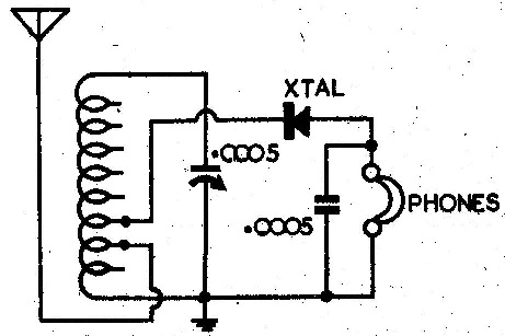
CRYSTAL SETS
These radios only have about 4 parts in them, so they are easy to fix, but also hard to fix, as each part must perform to a high standard. The most important item is the tuning device, which can be a coil and variable capacitor, or just a tapped coil (using self capacitance). Some designs may use a variometer, which is one rotating coil inside another. The 2 coils assist or oppose and vary the inductance. The Q of these coil must be high to get loud stations and sharp tuning. There was a lot of thought put into coil design, and the basket wound coils with Litz wire (multi-stranded) using air core with no former, performed the best. The detector could be a galena crystal (cat's whisker) or germanium diode. Silicon diodes work fine in the metropolitan area. The headphones must be high impedance, so as not to load the circuit. If the headphones are low impedance, use a speaker transformer as a matching transformer. Any speaker transformer will do. A large aerial and a good earth are essential.
The easiest way to check the coil is with a grid dip meter. It can tell you the resonant frequency, and (by the suddenness of the dip) a rough indication of the Q (quality). Common faults are corrosion of the wire. If all the stations are cramped up one end of the dial, then the self capacity is too high. If the coil is wound with cotton covered (CC) wire or double cotton covered (DCC) wire, check for moisture in the covering. Gently drying it in the sun is the best way. Insulating the coil with glue or spray lacquer may reduce the Q. Check the variometer axles and connecting wires.
Common headphone faults are an open circuit coil due to corrosion. Rejoin or rewind the coil. Check for faulty leads. Tinsel wire is hard to rejoin. To fix it place some fine strands of normal copper wire in the join, then bind it with cotton, to match the covering. It works sometimes. The ends can be terminated, by winding fine tinned copper wire around them, and then soldering. Check and clean the metal diaphragm. A special hardened steel is used. Transformer laminations can be used, but they are usually not wide enough.
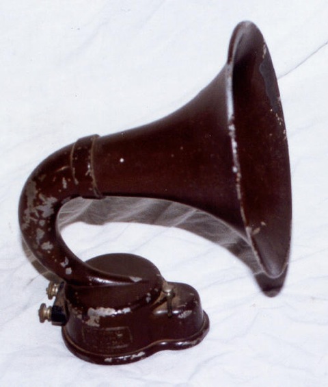
HORNS
A radio horn is just the same as a single headphone, except it is heavier duty and it has a large metal tube of increasing cross section. The horn couples the sound from the headphone like driver, to the air. The horn can be metal or wood. Be careful as the horns that are usually used on radios, are connected directly in the amplifier anode circuit, and so have HT on them. The driver suffers the same faults as headphones. Check the horn for blockages, or air leaks as the sound can escape and reduce the volume. This is important for wooden horns.
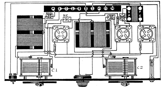
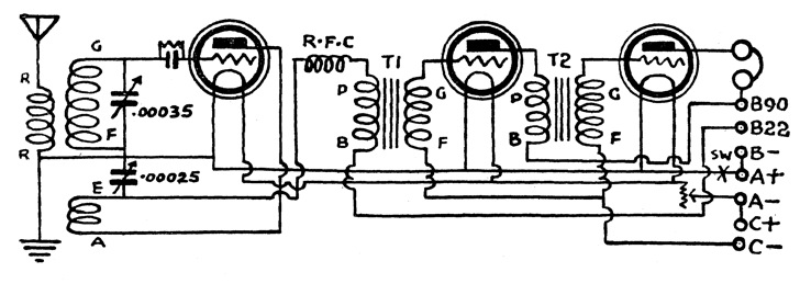
T.R.F. RADIOS (Tuned Radio Frequency)
These sets are very simple and can be regarded as an amplified crystal set. They may have one or two RF stages and one or two audio amplifiers. The TRF, due to their time of manufacture, used directly heated valves, so there was no cathode, and therefore no way to make cathode bias. The grid bias had to be generated from a C battery (in battery TRF sets), or a C supply, or back bias (in a mains powered set). Another method, was to ground the positive side of the filament, and use the negative side as the grid return. This was the age before ganged tuning capacitors, so each stage had a separate single gang tuning capacitor. The detector is commonly an anode bend detector, or a grid leak detector. The anode bend detector is merely an audio amplifier with no bias. The audio stages usually have a negative or C bias supply. The grid leak detector is a capacitor and high value resistor in parallel, the combination providing the detection. The RF coils should be at right angles (or well shielded) to prevent coupling between stages. There was sometimes a resistor in the grid lead as a "stopper" to prevent oscillation. Another method was "neutralisation" which required some feedback from plate to grid, usually by a small capacitor. The gain of these radios was set by a filament rheostat, which adjusted the filament voltage, and the gain. On some sets, there was a filament rheostat and a tuning condenser for each stage, resulting in lots of knobs. The sets often used headphones, or a horn loudspeaker.
The most common fault in a TRF battery set is burnt out valve filaments, as it is very easy to connect the A and B leads wrongly. A common fault in the detector is a high or open circuit grid leak resistor. Faults in the RF stages are often open circuit windings and dirty wipers on the tuning capacitors, caused by the age of the sets. Audio faults are often open circuit transformers. Also look for corrosion on the valve sockets and wiring. If the construction method is bare copper wiring, to bolts or screws on the valve sockets, clean these. If oscillating, check the grid stopper resistors. Check that the coils are connected the correct way. Check that it is not a regenerative circuit and is supposed to oscillate! To neutralise a stage, tune to a station, remove the filament voltage of that stage, and adjust any neutralising control for MINIMUM volume, because the neutralising control works by producing negative feedback to counter any capacitive coupling in the valve.
REGENERATIVE RADIOS
These detectors were common in the 1920s and also for home made radios. The radios used an almost oscillating detector followed by audio amplifier stages. They relied on feedback to increase the gain, but needed careful adjustment, so that they did not break into oscillation, and turn into transmitters, using the radios aerial. There was fear in the war, that ships with these types of radios, would broadcast the location of a convoy and attract enemy attack. Some care was taken to avoid this by adding a filter or RF stage between the aerial and the radio. Screening of the local oscillator in a superheterodyne was elaborate in some maritime receivers. These sets were easy to use. Just turn the reaction up full, then tune across the band, and each station appears as a whistle. Stop on the one you want, then back off the reaction control. The design problem was to make the drop into oscillation gentle, as if it was too quick, it was difficult to stay at the maximum loudness point, and out of oscillation.
Common faults with these, are no oscillation, due to a valve loosing emission, or components aging. If the drop into oscillation is too quick, then reduce the screen or plate voltage. If it won't oscillate, and someone has been working on it, check that the reaction winding has not been connected backwards. Faults in the audio section were usually open circuit audio transformers.
SUPERREGENERATIVE RADIOS
These detectors are similar to a regenerative radio, except that they have automatic oscillator control. They are not often used except in shortwave or amateur applications or in modern keyless entry systems. Their main use is simple VHF radios. They work like a regenerative detector at the threshold of oscillation, but have additional circuitry to control the oscillation, called "quenching". The quench is also an oscillating type of circuit, that usually runs above the range of hearing, typically 30khz. It can be in the same circuit, or be an external valve. When the regenerative circuit is about to break into oscillation, the quench circuit stops it. Thus the circuit is operating like a regenerative detector, at its most sensitive point. There are several drawbacks. The circuit is difficult to design and keep working. It has a broad frequency response. It always has a "rushing" sound in the audio output.
This type of detector is difficult to fix. The most common faults are low emission valve, and faulty capacitors. If the circuit has an external quench circuit, it may be easier to fix this first, then the main circuit. Alternatively, defeat the quench circuit and fix the regenerative detector so that it oscillates. Sometimes, the circuits are so interactive, they cannot be separated.
Section 1
Section 2
Section 3
Section 4
Section 5
Section 6
Section 7
Section 8
Section 9